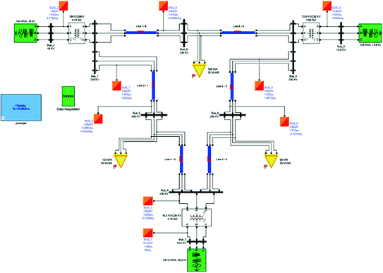

If the impedance diagram is to be used to determine the current immediately after the occurrence of a fault, the induction motors are taken into account by a generated emf in series with an inductive reactance. Since the generated ems of synchronous motor loads contribute to the fault current, they are always included in making fault calculations. Static loads (i.e., the loads which do not involve rotating machines) have little effect on the total line current during a fault and are usually omitted. Since the resistance of a syste is very small as compared to its inductive reactance, the resistance is often omitted when making fault calculations. The shunt admittance is usually omitted in the equivalent circuit of the transformer because the magnetizing current of a transformer is usually insignificant compared with the full load current. Medium and long lines are represented by nominal PI circuits, whereas very long lines are represented by equivalent PI circuits. A short line is represented by its series impedance. Transformers and motors are represented by their equivalent circuits. Representation of Power System Components on the Single Line DiagramĪ generator is represented by an emf in series with an impedance. The equivalent circuit of the system drawn by combining the equivalent circuits for the various components shown in the one-line diagram is known as the impedance diagram of the system. In order to analyze a power system under load conditions or upon the occurrence of a fault, it is essential to draw the per-phase equivalent circuit of the system by using its one-line diagram.

Three phases are denoted by a single conductor i.e., power system is assumed in a balanced steady state.


 0 kommentar(er)
